Piston motor with magnetic drive and shield
1. Description of the Invention
On this website the principle of a new engine concept is described. With a simple engine concept, the inventor proposes in his patent application (DE102014012297.2), to drive a piston engine with strong permanent magnet and a suitable shielding with large torque, as is common in conventional internal combustion engines.
With magnets and a shielding system, a linear movement of piston is realized. A ferromagnetic metal as a pull rod, which is attached to the piston, is tightened with strong permanent magnets and by shielding of the magnetic field having a rotor, the magnetic field acting on the tie rod is attenuated and the up and down movement of the piston is converted into a rotary motion with a crankshaft.
It is known to set the crank in a rotary movement with reciprocating engines. In combustion engines, the volume change of a gas is turned into a rotary motion through linearly moving cylindrical piston via a connecting rod and a crank. Common examples of internal combustion engines are the gasoline engine and the diesel engine in automobiles.
Meanwhile, there are permanent magnets made of rare earth metals with very high adhesive force. In industry, for example, lifting magnets made of permanent magnets of the supporting force of several tons weight are used for lifting and transporting of ferromagnetic materials (see e.g. the web).
In the present invention, a strong tensile force is exerted on the piston with a neodymium permanent magnet (NdFeB). Neodymium magnets with very strong magnetic fields are available on the market. Cubic Neodymium Magnets N45 with dimensions of about 11x9x2 cm for example can carry about 800 kg with its magnetic field (see e.g. here). By using a plurality of magnets of this type, the magnetic field of the present invention is multiplied and the torque necessary for the effective operation of the piston engine is realized.
The piston engine comprises a crankcase according to today common design, however, the cylinder head which closes the combustion space of an internal combustion engine is not used. The classical components of the crankcase with the crankshaft, connecting rod and piston with the cylinder liners may be used in the present invention.
In contrast to a conventional piston engine, the piston engine in the present invention instead of the cylinder head includes permanent magnets that are arranged in parallel and a rotor having discs for the shielding. The discs are made of mutually different diagonal segments, preferably made of iron and aluminum. The diagonal circular segment with the iron causes the shielding and the segment with the non-magnetic aluminum forms the magnetically neutral area.
The overhead shaft of the rotor is connected and powered either with gears, a timing chain or a timing belt with the ratio suitably chosen with the crankshaft. The diagonal shield segments of the discs are adapted to the respective piston positions.
The new engine principle is described below, using the animations and drawings, that are merely illustrative and are not limiting. Here, a shielding device with a rotor is described, but in the patent application further embodiments of the invention have been described with embodiments.
Animation 1:
The so-called super magnets have an adhesive force of several hundred kilograms. A neodymium magnet can, for example, carry a weight of 100 kg and two magnets can therefore carry twice the weight.
The so-called super magnets have an adhesive force of several hundred kilograms. A neodymium magnet can, for example, carry a weight of 100 kg and two magnets can therefore carry twice the weight.
Animation 2:
Two magnets are arranged so that they can move a piston with their force of attraction. A piston is connected to a drawbar and attracted by the strong magnets. However, the piston would lock and not move anymore.
Animation 3:
With a suitable device, e.g. with a rotor as shown in the animation, it is possible to weaken the magnetic field in the direction of the drawbar, and the piston may move down.
Animation 4:
For a piston to be able to move downwards during magnetic shielding, another piston must move upward by magnetic attraction.
Figure 5:
The principle of magnetic attraction and shielding can be extended on the basis of the basic construction of motor variants from different numbers of cylinders, cylinder assemblies and shielding systems. For different applications, the construction of the motor system can be adapted to the requirements as shown in the following figures.
2. The principle of shielding
Using the following figures, the principle of shielding can briefly be described.
Using the following figures, the principle of shielding can briefly be described.
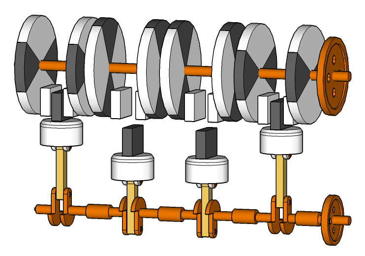
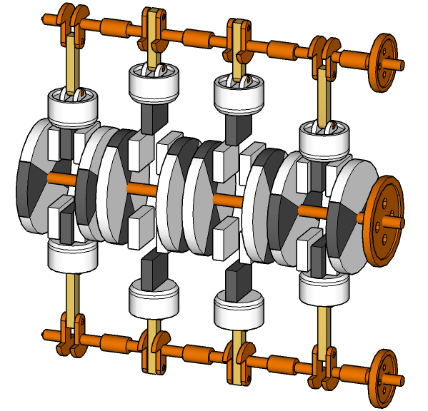
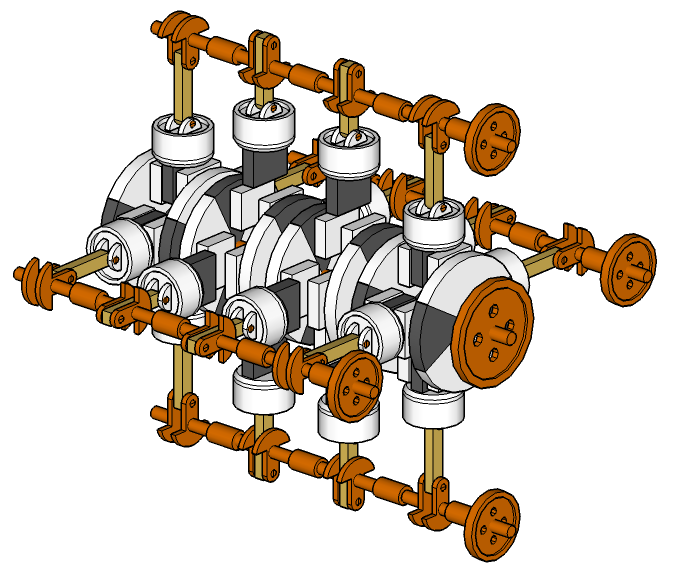
Figure 6:
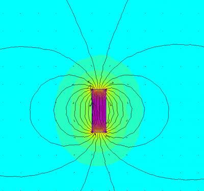
Magnetic fields propagate in three dimensions in space and depending on strength (magnetic flux density) are exponentially reduced with increasing distance.
Figure 7:
Another well-known property of the magnets is that they attract ferromagnetic materials such as iron. Magnetic fields are not static, but they can be moved by external influences. In this figure it is possible to see how to move the original magnetic fields in the vicinity of a ferromagnetic metal.
Figure 8:
The magnet pictured in the middle attracts the two side-mounted metals, but the attraction of the metal with the smaller dimension is weakened. For the metal given on the right this can easily be seen by the color in its interior (density of the field) compared to the previous figure. To ensure optimal functioning of the shielding, the ferromagnetic shield metal must have greater dimensions than the target object.
Shielding
The principle of shielding in the present invention is based on the general idea to deflect a specific magnetic field of the permanent magnets on a plurality of ferromagnetic objects of different dimensions and thereby weaken the magnetic field acting on the target object.
Each magnet is surrounded by a magnetic field, and a piece of iron is attracted by a magnet by means of the magnetic field partially being redirected to this iron. On two separate parts of iron with the same dimensions, the magnetic field is deflected to both, and the proportion of the magnetic field for each metal parts decreases. In two iron parts with different dimensions, the magnetic fields are, however, weakened at the iron with the smaller dimensions.
In the present invention, the magnetic field of the two magnets is first diverted to the drawbar with smaller dimensions and attracts it. The rotor consists of two shield segments, preferably made of iron with larger dimensions than the drawbar. In the vicinity of the magnets, the magnetic field of the permanent magnets in not only diverted on the drawbar but also on the double lateral shield segments of the rotor made of iron with a double thickness. Thus, the magnetic field is weakened on the drawbar and the drawbar can leave the magnetic field with the piston.
5. What is a perpetual motion machine?
The theme of "perpetual motion machines" often leads to misunderstandings and in assessing the present invention, this theme is also to be taken into account.
The definition
In Wikipedia a perpetual motion machine is described as follows:
"Perpetual motion is motion that continues indefinitely without any external source of energy.This is impossible in practice because of friction and other sources of energy loss. A perpetual motion machine is a hypothetical machine that can do work indefinitely without an energy source. This kind of machine is impossible, as it would violate the first or second law of thermodynamics."
In all physical processes energy is converted, and it is not possible to "create" energy.
This summary of the energy conservation law by me is often misunderstood. Since energy can not be "created", it does not mean that there are diverse and previously unknown possibilities to convert energy or forces into each other. And if a conversion process is not understood exactly, it does not mean that energy is created from nothing.
A few centuries ago, our modern technology as with mobile phones, television, internet, cars, etc. would also had occur like magic for our people. Whereas, these technologies are based on simple physical principles that are used with great technical knowledge in the devices and machines.
The engine concept presented here, according to the general definition, of course is not a perpetual motion machine, and the energy used consists of strong magnetic fields. This energy can be converted by suitable design in mechanical work. It does not generate any energy out of nothing, but the permanently existing attractions force of magnetic fields are converted into mechanical work.
A magnet with an adhesive force of 100 kg for example at direct contact may exert at most an attractive force of 100 kg and carry no weight of 200 kg, because only a limited magnetic field strength is available and no energy or magnetic force can be generated from nothing.
The Magnetism
Among the many other forms of energy and forces in the universe, magnetism (as well as gravity) has a special place. Permanent magnets exert forces with their permanent magnetic fields, however, the magnetism is always preserved, i.e. magnetism can not be consumed. After a conversion of magnetic energy into mechanical work, the magnetic fields are available again for re-conversion. It would be physically correct, if one would say that the magnetism under normal conditions decreases very slow and barely noticeable, because everything is impermanent in universe.
These physical aspects of magnetism are known for a long time, but they are hardly taken into account in detail in the description of perpetual motion machine in the first, second and third kind, as well as energy conservation laws and thermodynamics. Although the magnetism is also subject to these universal physical principles, these laws historically are rather described in cogeneration processes, in which the supplied energies and forces actually get lost in the conversion process, and where for the re-conversion, new energy must be supplied from outside.
From these points of view, the energy conversion process using magnets is more comparable to the nuclear reactors. In the energy conversion in the nuclear power plants, no energy is continuously supplied from the outside, but the energy in the uranium nuclei is released during nuclear fission by a nuclear chain reaction and converted into thermal energy.
Due to its special position, magnetism is something to consider differentiated during its assessment. According to the above description of perpetual motion machine in Wikipedia, energy in the permanent magnetic fields for permanent magnets corresponds to "externally supplied energy" during the energy conversion. Therefore, analogous to the nuclear power plants future plants which will use the magnetic force for energy conversion, may be described as "magnetic force plants".
During the use of magnetic forces, their special properties are to be observed. It is currently difficult to exploit the idiosyncrasies of invisible magnetic fields technically and requires not only extensive technical and physical knowledge but also a special intuition. In view of the fact that nowadays there are very strong permanent magnets on the market, the trick is to convert the immense magnetic forces into mechanical work with a shielding through appropriate constructions and designs.
Taking into account the general description of perpetual motion machines, analogous to nuclear-energy magnets, in principle it is possible to construct a machine that converts the forces of permanent magnetic fields into mechanical work. Here, the question arises as to how to permanently convert the magnetic forces into mechanical work using the permanent magnetic fields, while despite the losses still divert sufficient usable energy. To answer this question several physical factors must be considered, because all physical processes are coupled to each other and no process takes place in isolation without interaction.
If a process of transformation processes of energy / forces only is reduced on certain aspects, it cannot be understand exactly. It would also be disastrous to come to wrong conclusions out of ignorance or excludes any possible options at first.
Example:
If mechanics is reduced on some components and forces, then the current technologies is obtained and as of the gasoline engine, the principle is based on a centuries old idea. In alternative new technologies it is possible to penetrate into areas that are largely theoretically known, but the complex relationships among themselves were sometimes poorly explored.
The movement of a piston with magnetic force is for example depending on the following physical factors:
- Gravity (gravitational attraction of the earth)
- Centrifugal forces (acceleration)
- Mechanical forces (for transmission)
- Magnetic forces (mass attraction by magnetic fields)
- Structure of Matter (magnetism of atoms)
- Friction forces (losses in energy conversion)
- Air pressure and temperature (thermodynamic influences during energy conversion)
- Local gravitational acceleration (the gravitational force is dependent on the location)
- Material properties of the components (each material has different properties)
- Electrostatic interactions (charge/ load transfer in bodies)
- Synchronization of processes (temporal cause-and-effect principle)
- Vacuum permeability (propagation of magnetic fields in space)
- Electromagnetism (magnetic fields on moving charges)
...and much more, apart from quantum effects in atoms and factors that we do not yet know.
Many of these factors have very minimal impacts and are therefore not included in the mechanism, but ultimately the interplay of these various physical factors leads to conversion of energy. With a careful analysis and fine-tuning of the above-mentioned physical factors, it is possible to better understand and optimize the energy conversion process. No energy is created from nothing, but it is desired to convert a small portion of energy into usable energy during energy conversion (see example in section "3 FEM").
Contents of this website:
1. Description of the Invention
2. The principle of shielding
3. FEM-calculations
4. Development potential
5. What is a perpetual motion machine?
6. Magnetism as an energy source
7. Important safety notice
1. Description of the Invention
2. The principle of shielding
3. FEM-calculations
4. Development potential
5. What is a perpetual motion machine?
6. Magnetism as an energy source
7. Important safety notice
Animation 1
Animation 2
Animation 3
Animation 4
Figure 5
3. FEM-calculations
FEM calculations (Finite Element Method) in the present invention provide a sufficient weakening of the magnetic field in order to ensure a continuous linear movement of the individual pistons. The most part of the attraction force acting on a piston is used in order to rotate the rotor and the other pistons and does not generate a torque on the crankshaft, however, the residual attraction force is sufficient to produce the necessary torque.
The efficiency factor is as a measure of the efficiency of power changes and illustrates the ratio of the supplied power. In the present invention, the theoretical efficiency factor is low in terms of energy conversion, but nevertheless the rest of the mechanical forces can be used for drive purposes. Much of the magnetic fields' supplied energy is lost, but as this magnetic force does not cause an costs, it also has no economic importance.
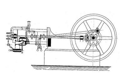
Figure:
Gasoline engine from 1879 (Patent Drawing).
Nikolaus August Otto, to whom we owe the Otto (gasoline) engine, incidentally, was not an engineer, but an traveling salesman of a Cologne "Colonial trade of goods".
Gasoline engine from 1879 (Patent Drawing).
Nikolaus August Otto, to whom we owe the Otto (gasoline) engine, incidentally, was not an engineer, but an traveling salesman of a Cologne "Colonial trade of goods".
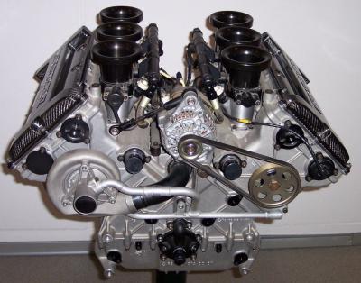
Mercedes-V6-Racingengine
(Source:Wikipedia)
(Source:Wikipedia)
7. Important safety notice
The use of the presented technique is at your own risk. It is referenced to the disclaimer at the following link. Disclaimer
In order to achieve the necessary torque at the engine concept presented here, very strong permanent magnets with high field strength are necessary. Already during the sale of these so-called "killer Magnets" attention is drawn to the risk of injury. It is therefore not advisable to recreate the presented engine in domestic workshops. The dangerous magnets must be placed very close together and special tools are required for the handling of the strong magnetic forces and special safety measures must be observed.
Also, for technical reasons, a private replica is not worth it, because some details have to be optimized by professional construction with other ideas of the inventor previously kept confident.
The present invention is a complex technology and, accordingly, the construction of the prototype is complex and expensive. It therefore is not feasible with hobbyists tinkering and the objective can only be achieved with professional project work.
I am also pleased with your questions, suggestions and criticism. Please use the following email address for this purpose:
Download the contents of this website for internal purposes as a PDF file.
The magnitude of the torque in the present invention is inter alia depending on the magnetic field strength of the individual permanent magnets, the size, shape and material of the pistons, the drawbar and the shielding system as well as the distance between the individual components. In the construction, therefore some technical hurdles are to overcome, but that is also necessary with new, innovative technologies, because this is the only way to obtain a technical advance. Besides of a construction accurate in millimeters, also the specific characteristics of the magnets are to be taken into account.
Attractive forces on the piston position
The following is an analysis chart that is given for illustrative purposes. With the finite element method (FEM), the magnetic attraction forces in two pistons was determined according to piston positions in two cycles (up and down).
The y-axis shows the attraction force and the x-axis shows the individual time segments. The black vertical dividing line in the middle of the diagram shows the transition of the shielding on the piston per cycle.
Example:
In a 4-cylinder engine according to the present invention there are used 8 Super magnets (two for each piston) with the total adhesive force of e.g. 8 x 800 kg = 6400 kg. The power transmitted on the crankshaft from four piston is only estimated to be about 200 kg. The maximum load capacity of 6400 kg of the magnets is mostly lost, but the remaining 3% are sufficient for effective operation of the engine.
Torque calculation
Above, weight was physically incorrectly specified as load capacity (generally is used by the suppliers of the magnets in this way). However, for the calculation of the torque we do need to multiply the weight with the gravitational acceleration (approximately 9.81 rounded up to 10).
The force acting on the 4 pistons is: F = 200 kg x 10 = 2,000 Newton
In a lever stroke of 5 cm, the torque on the crankshaft is thus:
D = 2000 N x 0.05 m = 100 Nm
For comparison: some gasoline engines have a torque of about 100 Nm.

Red line:
The piston A is attracted upwards by the magnet, and in the middle of the magnets the magnetic attracting force reaches the peak. Then the attracting force drops and after the vertical division line, the attraction is attenuated by shielding, and the piston A moves down.
Blue line:
While the piston A carries out the above-described linear movement upwards, the force of attraction for the second piston B is reduced in the first phase (to the left in the diagram) by screening, and the piston B moves downwards in the opposite direction. After the vertical dividing line, the shielding at the piston B is annulled, and it moves upwards with growing attraction.
Black line:
The black line shows the difference of the attraction forces at the two pistons A and B. It is the resultant force, because for moving a piston, the force from the other piston is necessary and must thus be deducted. The black line shows the sum of the forces available for the shielding device and useful energy.
This diagram illustrates the relationship of forces at different piston positions. However, in this evaluation the force applied to move the screening device is lacking. This considerable force must be deducted from the resultant force (black line in the diagram). However, this evaluation is a two-dimensional finite element analysis, and the forces in the rotor, must -in contrast to the vertical piston movements up and down- be included in the horizontal axis.
With appropriate software, it is possible to simulate the entire movement and the interrelationships of the various forces through extensive FEA analysis in 3D. The shielding effect is also clearly visible in the above 2D graph.
A magnet exerts a particular attractive force pull on a ferromagnetic metal. To separate the metal from the magnetic field, the same force must be applied, because the magnetic attraction forces are equal in both directions. As can be seen in the above diagram, the attraction force on the piston is reduced to about half by shielding. With a suitable design a small portion of the remaining force (black line in the diagram), which is spent on the screening device, may be used as useful energy for rotating the crankshaft. The better the shielding device is optimized, the more useful energy can be recovered.
The reinvention of the engine
Videos of magnet motors
Here are some Youtube videos with magnetic motors:
Magnetic motor (Patent-Nr.: DE102007037186B3)
Perendev-Motor
Magnetic motor (Patent-Nr.: DE102005059652A1)
A piston engine is driven with electromagnets (solenoid engine).
Here are some Youtube videos with magnetic motors:
Magnetic motor (Patent-Nr.: DE102007037186B3)
Perendev-Motor
Magnetic motor (Patent-Nr.: DE102005059652A1)
A piston engine is driven with electromagnets (solenoid engine).
6. The magnetism as an energy source
With permanently available strong magnetic fields you have an inexhaustible energy source, and it depends on whether one better understands the relationship between physical factors and can technically use these. It is useful and desirable to conduct more research and development in this direction. In the present invention, novel approaches are described that will bring us a step closer to this goal.
The previously known and partly patented magnet motors, which are powered by permanent magnets, have the disadvantage that they have no sufficient power for conventional applications provide due to their constructions (see for example the videos at the end of this webpage). Also a screening of the magnetic field is either not provided or is not optimally implemented de to its design. The advantages of the present invention is the fact to generate high torques, such as the conventional internal combustion engines with strong permanent magnets and a shielding.
The problem with the commercial use of the magnetic force consists less of physical principles rather than our knowledge of this and our current technology. Nature provides the permanent magnetic fields as a source of energy and it is up to us whether we can find the necessary materials and constructions to benefit from this inexhaustible energy source.
Our current knowledge and technology has emerged largely in the last 100 years and much is still in infancy. In the future, there may be possible special magnets with properties that we can not even imagine today. We should therefore preserve our Optimism and contribute to the development of knowledge and technology.
The analogy of nuclear and magnetic force was further explained briefly above. Also during nuclear fission, initially we stood facing major technical challenges and also some scholars were initially not convinced of the economic use of nuclear energy. Today, however, we owe a significant part of our energy worldwide to this highly complex, but also very dangerous technology.
The renewable energy market is growing steadily, but we can not say that with our present knowledge we are already familiar with all opportunities for energy conversion. We can learn a lot from nature, and the universe shows us the diverse forms of energy conversion since ages.
The magnetism as an inexhaustible energy source provides us with great opportunities for our energy problems. Today's technologies for energy generation will sooner or later end up in art museums and the future belongs to the magnetic force technology. The magnetic force plants in an industrial scale can provide a large part of our energy in the future.
In terms of the magnetic force technology we now face similar challenges as originally in the nuclear power plants, which can only be tackled through craftsmanship knowledge and new creative concepts. We are still at the beginning of a new development process, and it depends on our will, whether we contribute to the development of knowledge and technology. With investments in breakthrough technologies we can deploy our capital and know-how useful and not only we but also future generations will benefit from these technologies and developments.
I even thought about the magnetism before creating my present invention. On the main page www.hc10.eu , I introduce my free PDF book "The theory of everything - The primal force of the universe". In my book, I do describe a fundamental physical formula and magnetism as the primal force of the universe.
4. Development potential
The new engine concept has huge development potential, and with the technical knowledge of today it can be optimized and brought to market in a relatively short time. Since the invention of the gasoline engine about 130 years ago, the technique of reciprocating engines has evolved tremendously. The presented basic design of the engine is therefore to be compared with the first gasoline engines, and by further developments, it will hardly be recognizable after some time, as the two images show below.
The present engine concept is primarily not an alternative for the internal combustion engine in automobiles, even if it looks like this and some components such as pistons and crankshaft come from the gasoline engine. The new engine concept is primarily about power generation and in later development phases it can be considered to be designed for vehicles. This concept is designed for continuous operation with constant torque and speed. The variable speed and compactness of the internal combustion engines is currently an additional technical challenge in the new engine concept. The new engine principle, for example, may be used as a hybrid solution for permanent charging of the batteries in electric vehicles. For this however, a completely new vehicle design is necessary.
For different applications, the construction of the motor system can be adapted according to the requirements. Over time, the combustion engine and electric motors can be replaced, for example, for the following applications through proper design:
- Drive generators to produce electricity
- Drive for vehicles, ships and unmanned aerial vehicles (drones)
- Driving of pumps and fans for air conditioners
- Driving of heat pumps for generating thermal energy
Download the contents of this website for internal purposes as a PDF file.

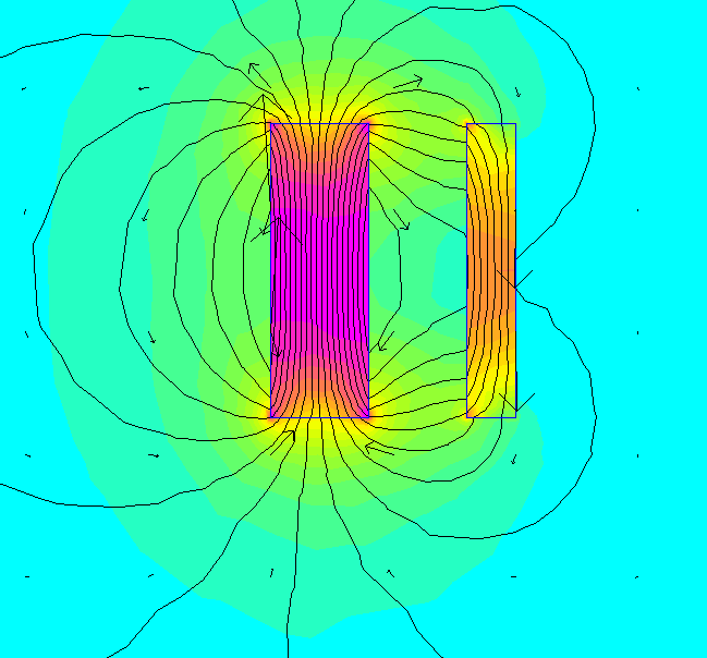
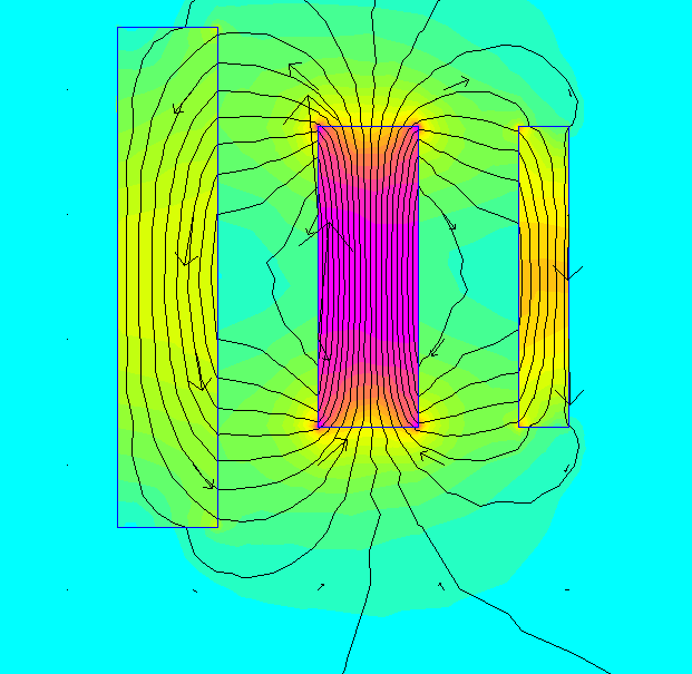
Figure 6
Figure 7
Figure 8